Vibratory Feeder Working Principles

How do Electromagnetic Vibratory Feeders Work? – Components & Principles
There are 3 varieties of vibratory feeder, which work on different principles. They are as follows:
- Electromagnetic Vibratory Feeder
- Natural Frequency Vibratory Feeders
- Out-of-Balance Vibratory Feeders
This article focuses on the working principles of electromagnetic vibrating feeders.
What is an Electromagnetic Vibrating Feeder?
Electromagnetic vibrating feeders are a common piece of equipment in many manufacturing facilities.
They are used as part of many processes, including conveying, screening, and packaging.
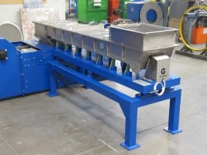
Electromagnetic vibrating feeders come in a huge range of sizes, from small desktop versions in laboratory settings, to conveying systems several metres long.
No matter the size, all these systems work on the same principle.
Working Principles
Like all vibrating feeders, an electromagnetic vibrating feeder moves product by making the feeder tray vibrate.
The product sits in the tray. When the tray vibrates, the product moves in a series of small hops. This series of hops combine to create the constant motion of the product.
The direction of movement is determined by the angle of the springs. The product will move up from the tray, perpendicular to the angle of the springs.
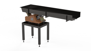
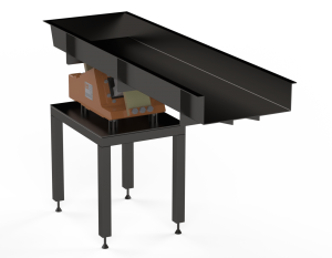
System Arrangement
The system is composed of a base unit, coil, flat springs, magnet, and a tray.
The tray is connected to the base unit by the flat springs. The flat springs allow relative movement between the two. It is this relative movement that will feed the product.
In simple terms, the coil (a magnet wound in copper wire to create an electromagnet) is attached to the base unit, and the magnet is attached to the feeder tray. The coil attracts and releases the magnet, generating the relative movement between the base unit and the feeder tray.
Drive systems are available that incorporate all the components of the electromagnetic drive (i.e. the coil, magnet, and springs) into a complete drive unit. A mounting plate is provided at the top end of the springs to add a feeder tray suitable for the application.
Generating Product Movement
The vibration of an electromagnetically driven feeder is generated as the alternating electrical current moves back and forward through the wires of the coil.
The magnet (attached to the feeder tray) is held a few millimetres away from the coil by the flat springs. As the current moves in one direction, the coil attracts the magnet and adds tension to the springs.
When the current switches direction the magnet is released, and the potential energy stored as tension in the springs is used to move the tray. This action throws any product in the tray forward creating the hop.
When this process is repeated at high frequency, a continuous flow of product is created.
Components
Springs
Achieving the correct relationship between the vibratory feeder tray and springs isn’t quite as simple as it might seem.
An electromagnetic drive will operate at a set frequency.
(Important Note: It is possible to alter the frequency of the drives with an inverter control system; this is discussed further under the ‘Feeder Control Systems’ section below)
It is important to try and set up the system so that the natural frequency with which the tray would oscillate on the springs matches the frequency of the electromagnetic drive. This will reduce stresses in the feeder tray and encourage product to flow as quickly and efficiently as possible.
The natural frequency of the oscillation is determined by the relationship between the combined total stiffness of the springs in the system and the mass of the feeder tray plus any product in the tray.
As the feeder tray and mass of product is largely determined by the application, and the electromagnetic drive (minus variable controls) will operate at the frequency of the alternating input (e.g. mains supply at 50Hz), the design variable is the springs.
Increasing the number of springs, and the width and thickness of the spring will increase the spring stiffness. The length of the spring is also a factor; longer springs are less stiff.
Feeder Tray
The main purpose of the feeder tray is to channel the product being fed to where is needs to go.
To achieve this, aside from being shaped to contain the product and prevent spillage, the tray needs to transfer as much of the energy generated by the drive, into the product as possible.
This is achieved by having a rigid feeder tray, which is determined by the design of the tray.
A tray which is not rigid will lead to areas of the tray vibrating at different frequencies, called secondary vibrations. These areas create anomalies in the flow of product, meaning product can slow, stop, or even run backwards.
Base
As well as being the lower mounting point for the flat springs, the base serves another essential purpose.
The mass of the base counteracts the movement of the feeder tray, and prevents vibration from the system transferring into supporting structures, which over time could lead to serious structural damage.
The base moves equal and opposite to the tray.
To keep the base secured to a supporting structure, it is connected to the structure using flexible rubber blocks. These blocks, while being stable enough to guarantee safety and stability during operation, do allow some movement of the base relative to the supports.
During normal operation, the feeder tray will vibrate at an amplitude of approximately 1.5mm.
This movement in the base would be too much for the rubber blocks to absorb.
To reduce the movement of the base, while still compensating for all the movement of the tray, the mass of the base needs to increase.
The relationship between the movement and the mass is inversely proportional, so to reduce the movement of the base by half relative to the tray, the mass must be doubled.
Typically the feeder will be designed to keep the movement of the base to below 0.5mm in any direction (although different blocks will be designed to allow greater ranges of movement), so for a high frequency feeder with a tray amplitude of 1.5mm, the base would be 3 times as heavy as the tray plus any product. The calculation is:
Base Mass x Base Amplitude = Tray Mass x Tray Amplitude
X x 0.5 = 1 x 1.5
X = 1 x 1.5 / 0.5
X = 3
So the ratio of the mass of the tray to the mass of the base in 3 : 1.
For feeding systems with higher amplitudes, ratios of up to 8 : 1 can be required.
Feeder Control Systems
As a vibrating feeder is a relatively simple piece of equipment, the control requirements are small.
Once a feeder is set up to perform it’s intended function, control requirements are usually limited to ‘stop’ and ‘start’.
This type of control is common when the feeder is controlling the flow of product into a process further down the production line.
Feeder Control Application
An example of this would be when the feeder is discharging onto a multihead weighing system.
As the multihead weigher can only process a finite amount of product, the feed onto the weigher will need to be paused.
Sensors on the multihead weigher will detect when the level of product on the weigher is getting too high. Based on this input, a signal is sent to the feeder to stop.
As the level drops off as product is processed, the feeder will re-activate.
Variable Speed Control
An additional measure of control can be provided by using and inverter.
The inverter changes the frequency of the feeder to adjust the speed of the product. A higher frequency increases the number of product hops per second and speeds up the product.
However, this method of control is limited.
As the springs of the feeders are tuned to work at specific frequencies, increasing the frequency above this effective range using an inverter can reduce the overall effectiveness of the feeder.
It is rare that a variable speed control function will be used during a production process. Product throughputs are usually much more dependent on actual processing equipment within the overall process, with feeder usually only moving product from one process to another.
One example of where the variable speed function might be put to use is where ingredients are being fed into a mixer and accurate measures of ingredients are required.
Under these circumstances, a feeder may be set to deliver the majority of an ingredient into the mixer at maximum speed, with the final few percent of product added at a reduced rate to prevent overfilling the system.
This article has covered some of the core principles of how electromagnetic vibrating feeders work.
If you have any questions about the systems, or are interested in what a vibrating feeder might be able to do for you, you can contact us using the form or details at the bottom of the page.
Have An Enquiry
Call our team of highly skilled engineers to discuss your requirements on 01782 493127 or fill out our online enquiry form.
Enquire Today